Following our first battery of tests, we dismantled our AMD Vega: Frontier Edition card (which we purchased retail) to get a closer look at the VRM & power design, thermal design, card assembly, and sizes for everything on the board. The tear-down process is the first step to our inevitable hybrid mod of AMD Vega, which should determine the card’s headroom with the thermal limitation removed. We’re also using this as an opportunity to report rough die size measurements, HBM stack measurements, and mounting distances for the community.
Full review testing is still forthcoming, as we didn’t have the usual pre-release embargo period to look things over, but this will serve as our first official Vega: FE coverage. Our next round of coverage will likely be a VRM analysis by Buildzoid, which will be accompanied shortly by thermal/power testing and overclock/gaming testing. Production tests will land in there somewhere – those are already half done – we just need to figure out where they fit best, based on content scheduling.
How to Disassemble the AMD Vega: Frontier Edition Card
Disassembly isn’t too hard. Because this was our first time taking apart the Vega: FE card, and because it has new construction from previous AMD cards, we had some extra steps in the video that would be unnecessary for removing the shroud + baseplate. Still, having now taken apart and re-assembled the card twice (following the initial video), we can show the best way to access everything.
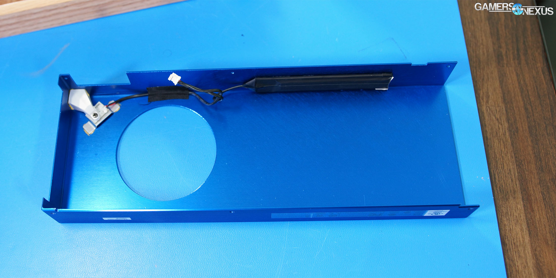
If the goal is to access the heatsink & fan part of the card, it’s best to start with the TR5 (Torx) screws on the outside of the anodized aluminum shell. There are about 5-6 of these screws. Removal of these screws will free the shroud from the baseplate, permitting removal of the shroud and exposure of the blower fan, baseplate, and heatsink. The backplate can be removed with a TR6 bit, with another 6 screws to pull out of the card. Next, a set of Phillips screws (PH01) are revealed under the backplate, three of which secure the blower fan to the PCB front-side. Remove the three screws in the triangle formation near the center-left of the card (back-side of the PCB facing you), then remove the other PH screws that secure the baseplate. The final four screws are for the retention bracket on the GPU cooler, which comes off in a single piece. The screws are captive.
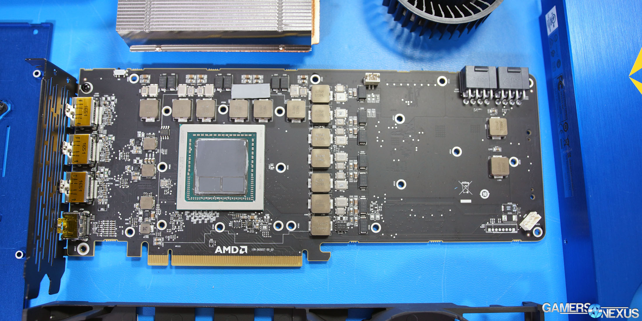
At this point, it should be possible to remove the cooler, the baseplate, disconnect the fan & LED cables, and expose the GPU.
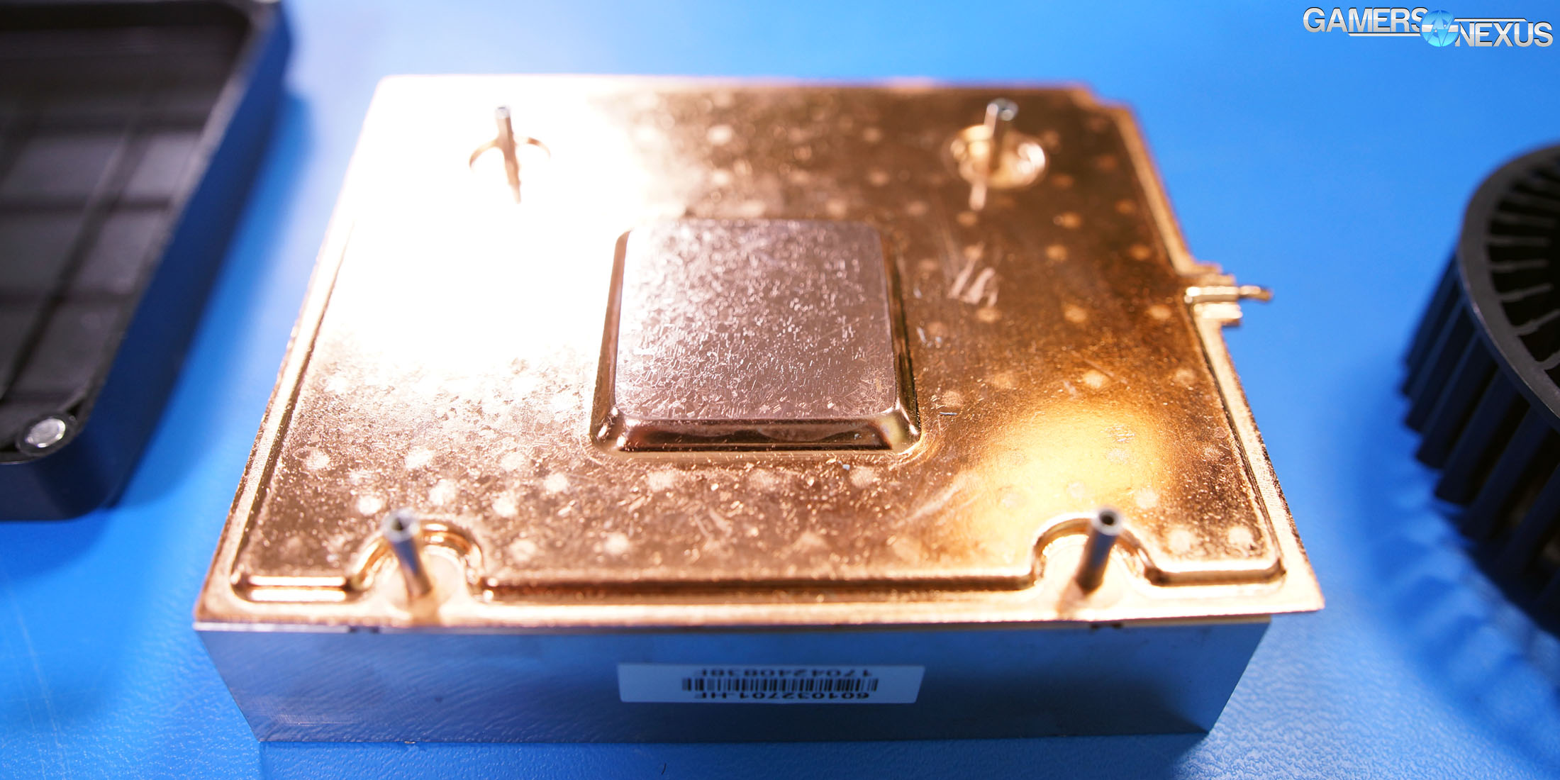
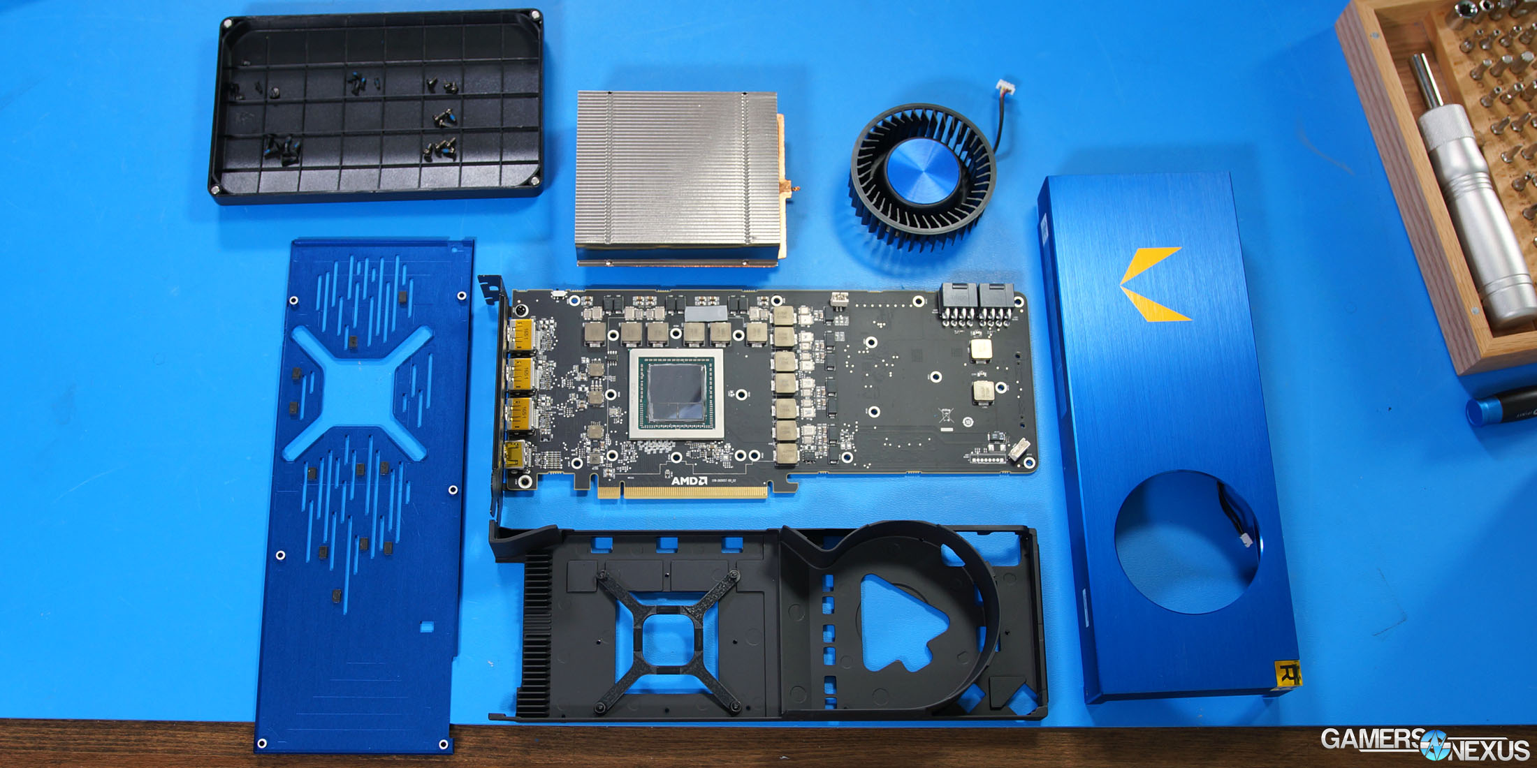
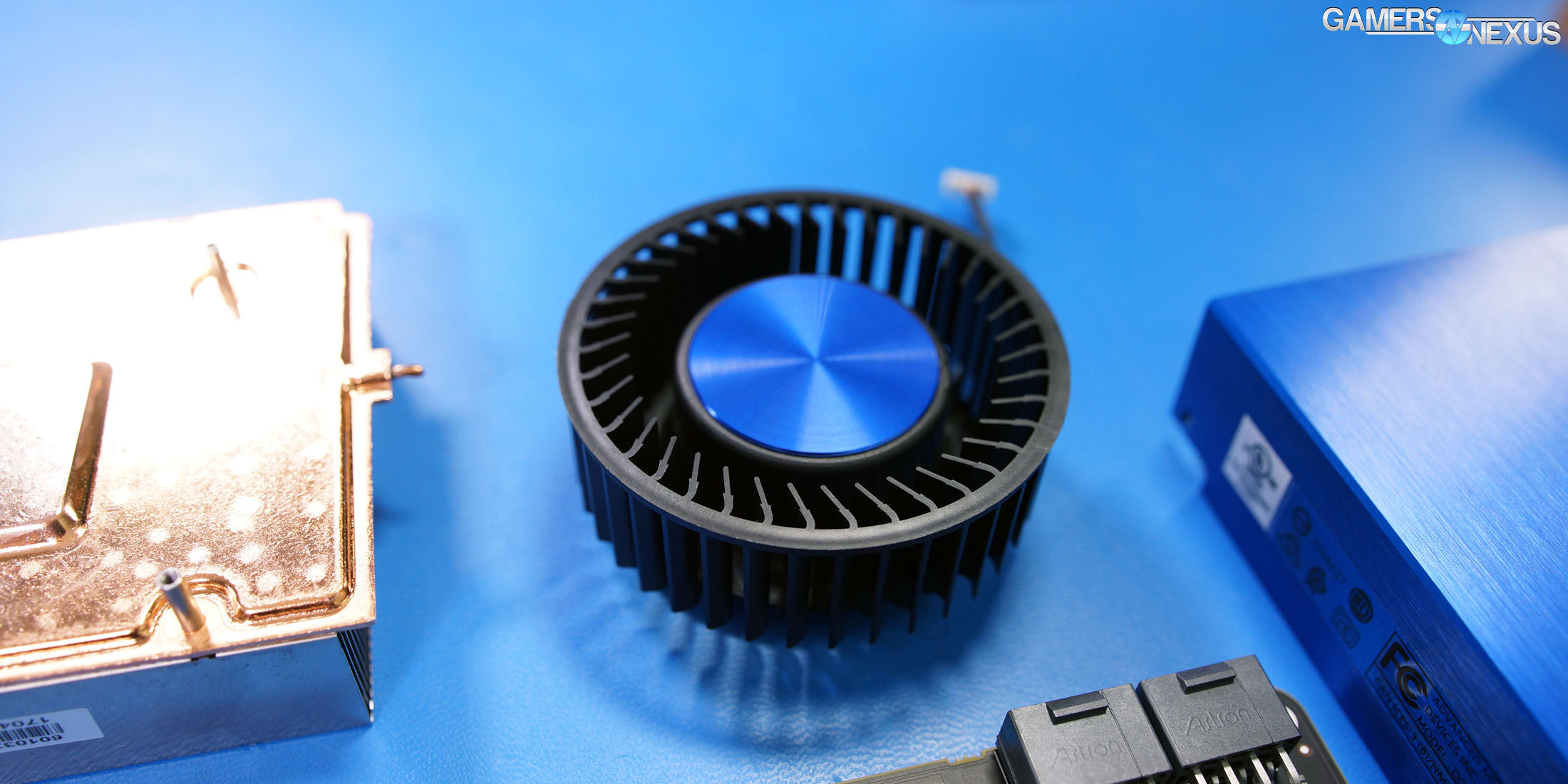
That’s it. The baseplate has some thermal pads for the FETs & inductors, alongside some fins near the DisplayPort & I/O, but is otherwise plain. The cooler is a large, aluminum block with standard 90-degree fin pitch and standard fin density, using flat-top fins to force air through the cooler block more efficiently. This exhausts out the back of the case, as expected. Conduction is handled by a copper protrusion in the copper baseplate, which covers both the GPU & HBM2 (two stacks). This is a vapor chamber cooler.
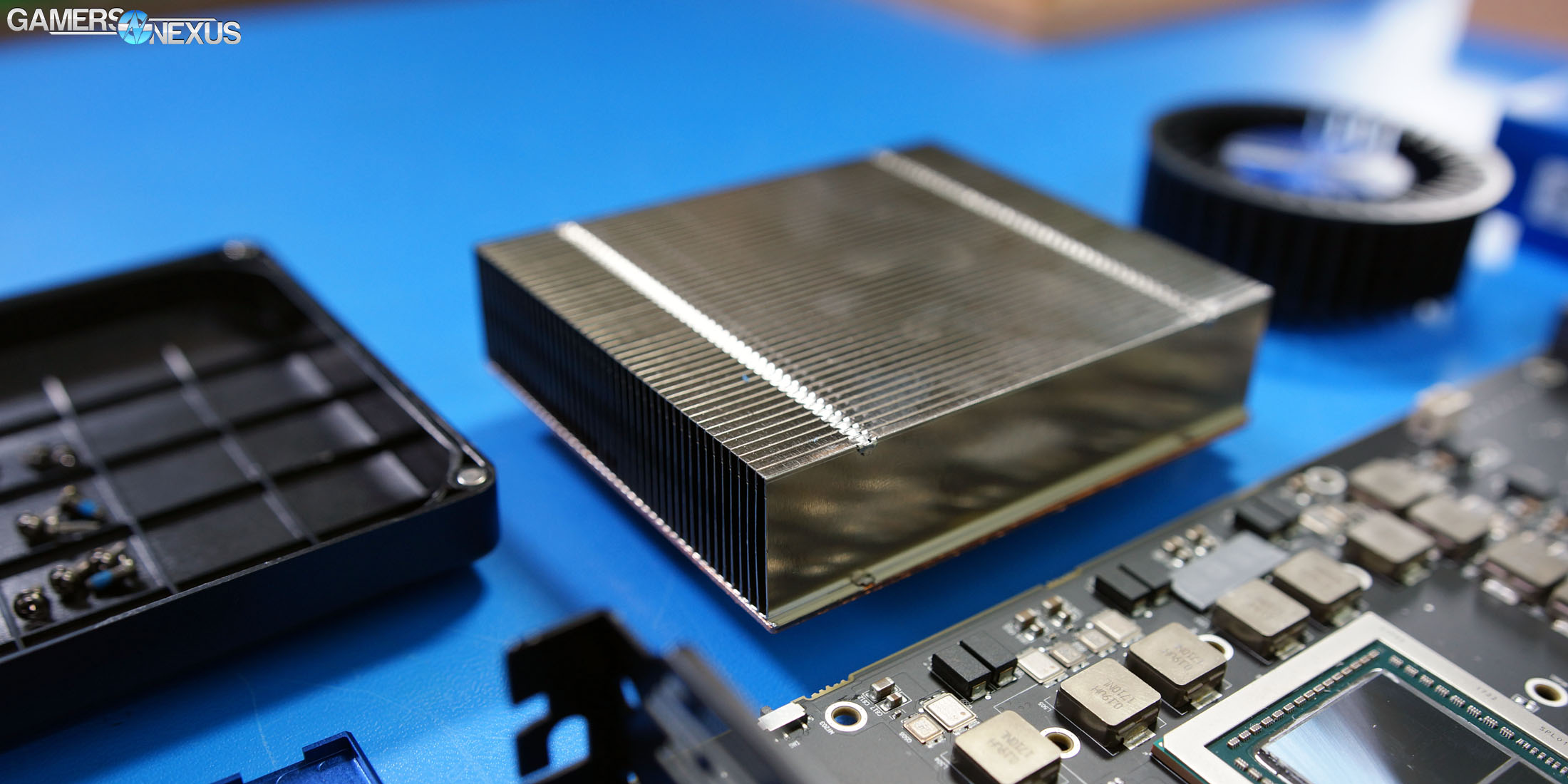
As for measurements, we took a pair of calipers to get some rough measurements. These may be off by 0.25-0.5mm. Here’s what we came up with:
- 30mm x 30mm total size of interposer + GPU (does not include substrate)
- 20.25mm x ~26mm GPU die size
- 10mm x ~12mm HBM2 size (x2)
- ~4mm package height (this is the one that’s least accurate, but gives a pretty good ballpark)
- 64mm x 64mm mounting hole spacing (square, center-to-center)
- PCB ~1mm
Our VRM & component-level analysis will come next, conducted by GN resident overclocker Buildzoid. Power, thermals, and noise will be around the same time for publication.
Editorial: Steve Burke
Video: Andrew Coleman