Under guidelines by AMD that we could show Threadripper CPU installation and cooler installation, we figured it’d also be pertinent to show cooler coverage on TR and RAM clearance. These all fall under the “installation” bucket and normally wouldn’t get attention from us, but Threadripper’s uniquely sized socket with uniquely positioned dies demands more instruction.
Threadripper thermal compound & coldplate coverage has been a primary topic of discussion since we first showed motherboards at Computex. We’ve generally offered that, theoretically, coldplate coverage should be “fine” as long as the two Threadripper CPU dies are adequately covered by the coldplate. In order to determine once and for all whether Asetek coolers will cover the IHS appropriately, seeing as that’s what TR ships with, we mapped out the dies on one of our samples, then compared that to CLC thermal paste silk screens, coldplates, and applied thermal compound.
Coldplate Coverage & Thermal Compound Spread
The silk screens are straight from the Asetek factory and are what we use for thermal compound application consistency between CLC reviews, in the event one has already been “used” from its factory condition. The coldplates were extracted from some of the many coolers we’ve dismantled, with the Asetek coldplate (from the EVGA CLC 120) representing effectively all modern Asetek CLCs on the consumer market. This would serve as a stand-in for popular coolers like the Corsair H100iV2, Corsair H115i, NZXT Kraken X42/X52/X62, EVGA CLC 280, Thermaltake Floe 360, Fractal Celsius S36/S24, Arctic’s CLCs, and more. Anything made by Asetek, which is something like two-thirds of the market, would fall under the guidelines of our silk screens and cold plates. We’ve also got one Cooler Master Seidon coldplate handy and, although its coldplate offers more exposed copper, the actual contact area and microfin area is about the same as Asetek’s unit.
Out of the factory, the footprint left by a standard Asetek-made CLC looks something like this:
This is small in comparison to the heatspreader’s total surface area, so we next need to understand how the coldplate overlays atop this:
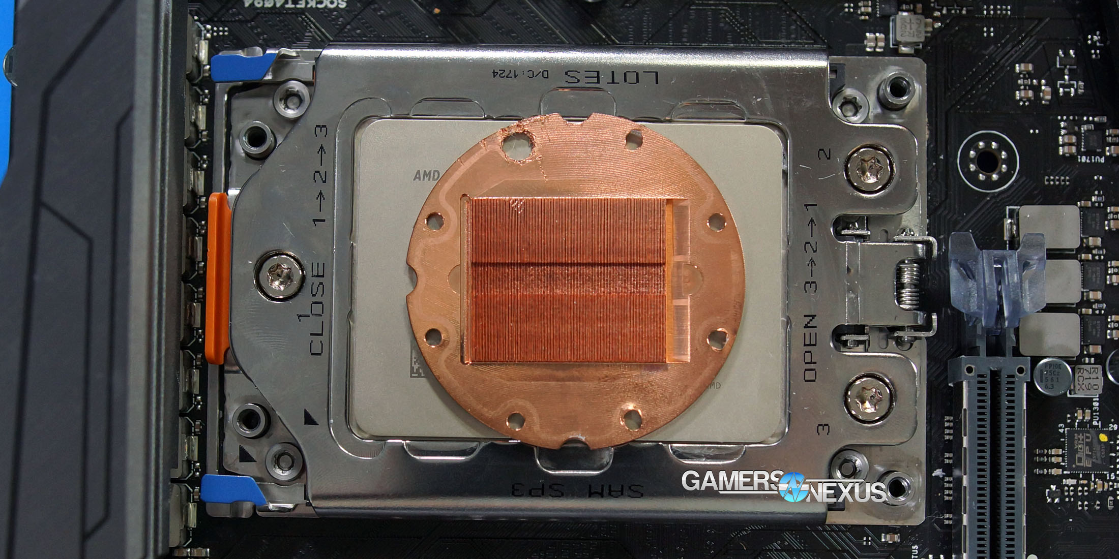
The coldplate covers roughly an additional 10mm radius. For most CPUs, both the coldplate and thermal compound coverage would be largely adequate to cover the die under the IHS. The entire heatspreader does not need coverage, theoretically, just the area with the silicon hotspots underneath; that said, covering more of the heatspreader certainly wouldn’t hurt – it does spread heat, after all, and increasing contact area to the cooling apparatus only stands to improve overall transfer efficiency and eventual dissipation. We’ll ultimately need to test this to come to any firm conclusion beyond observations for today.
Of note, there is an "optimal" orientation for the coldplate: You'd want the microfins long-ways across the widest part of the CPU IHS, as that'd ensure that the most thermal mass sits directly over the dies. We also run into concerns where the coldplate's most effective cooling area sits atop nothing of import -- the center of Threadripper isn't a die, it's spacing between dies. Typically, that center area would also be the center of thermal activity on a traditional single-die desktop CPU. That's why the cooling mass is focused over the center like it is, but that design doesn't apply well to Threadripper. Instead, we have two peripheral hotspots toward the outer perimeter of the coldplate. Although these Asetek CLCs may be adequate for cooling Threadripper, if only because of brute force, we also believe they are less efficient than they could be. There's a lot of room for other manufacturers to improve on this, given the unique parameters of Threadripper. And to be clear, this isn't a fault of AMD or of the cooler makers -- Threadripper and the coolers can exist independently as well-designed products, but that doesn't mean they can exist optimally together. But then again, we'll review it eventually. Can't carry this too far.
Those observations do provide a foundation, though: Here’s a look at the die location for Threadripper:
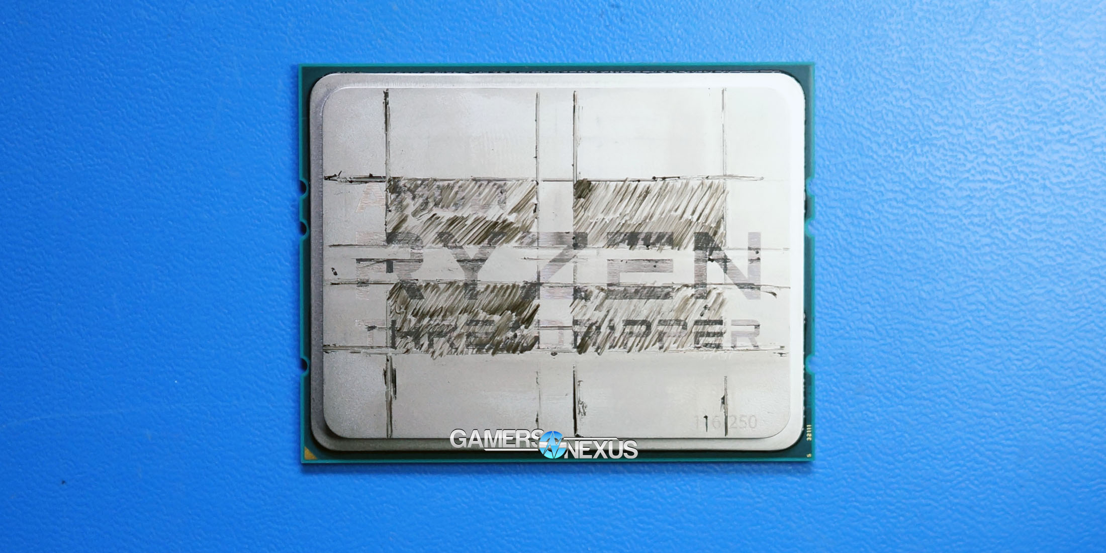
This was created using known specifications of Ryzen die size and by cross-referencing Der8auer’s delidded CPU image with our sample. We then drew the die location. Keep in mind that only two of these are active (and all four are inset ~12.5mm x 16mm from the substrate edges). Two of the “dies” are actually inert silicon substrate interposers, which effectively serve as spacers to ensure even mounting pressure across the surface. From what we’ve been told, the same two dies will be active on each Threadripper CPU. This means that two hot spots will exist underneath the IHS – one for each die – and that those two spots will be just along the border of the Asetek CLC coldplate. They’re technically within bounds, but we’re talking a millimeter or so of difference.
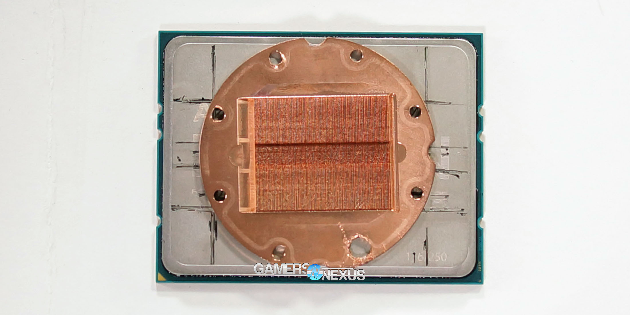
Part of each die will be exposed to indentations in the coldplate surface that are made for screws, which will lead to air pockets of high heat given poor conductivity of air (~0.03W/mK @ 25C). We haven’t yet tried this, but it may be a good idea to fill those screw holes with thermal compound to ensure a pocket of hot air isn’t formed directly over the CPU dies. It is normally unnecessary to add thermal compound to the circle of paste that comes out of the CLC factories, but might just generally be a good idea for Threadripper.
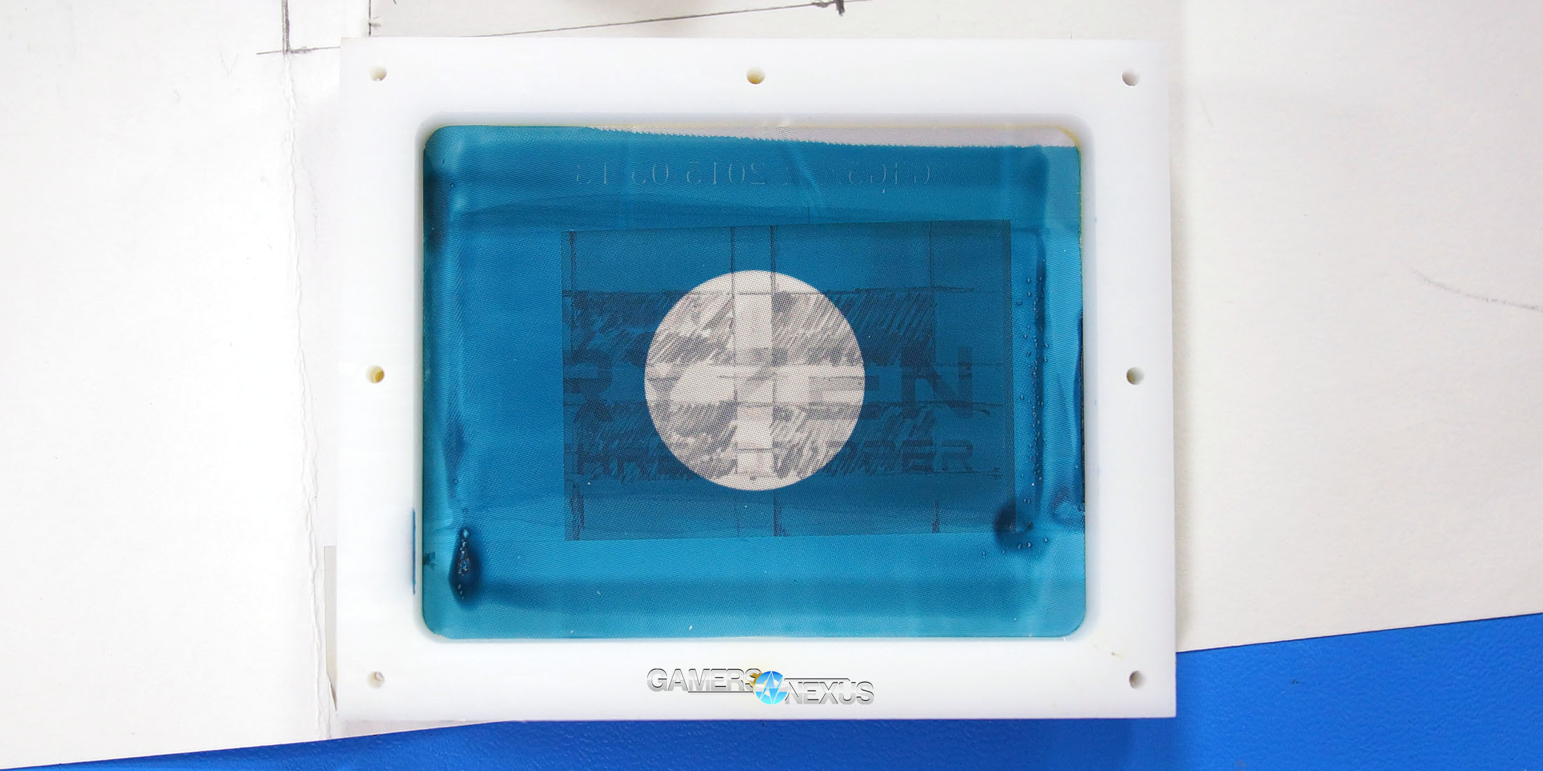
Above: One of the actual silk screens for Asetek Gen5 coolers, including Kraken X62, X52, X42, EVGA CLC 280/120, Fractal Celsius, and Corsair H100iV2/H115i coolers.
The stock thermal compound coverage appears sub-optimal, though should likely be “passing” with regard to thermal performance overall. A wider coldplate would improve overall contact between the heat spreader and the cooler and theoretically permit more efficient thermal transfer, but as the hotspots are covered, the biggest need is taken care of – getting heat away from the die as quickly as possible. Still, we think there’s a lot of room here for cooler manufacturers to build TR-specific coolers that would be more efficient at removing heat from the IHS. Whether or not any money is in that job depends on the size of the manufacturer and their perception of TR’s volume movement; Noctua, it turns out, seems to already have TR coldplates in the works. More mobile cooler manufacturers should be able to get things done. It’ll be harder to convince the large companies to make TR-specific coldplates, given the relative difficulty and cost compared to the creation of existing product lines.
Regardless, we’ll look into this. As usual, we’d recommend avoiding jumping to conclusions until data is actually permitted for publication.
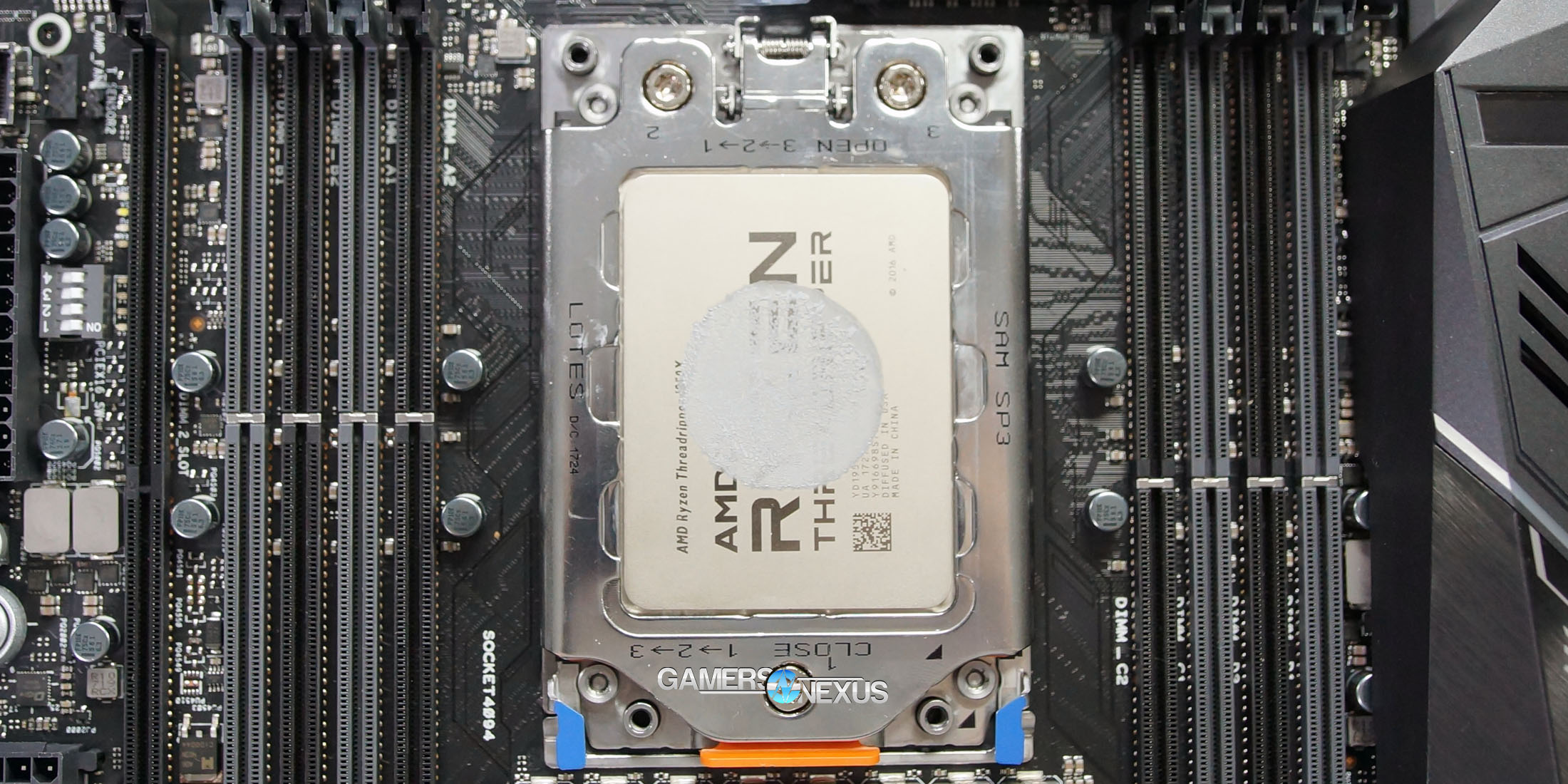
Installation of Threadripper CPUs
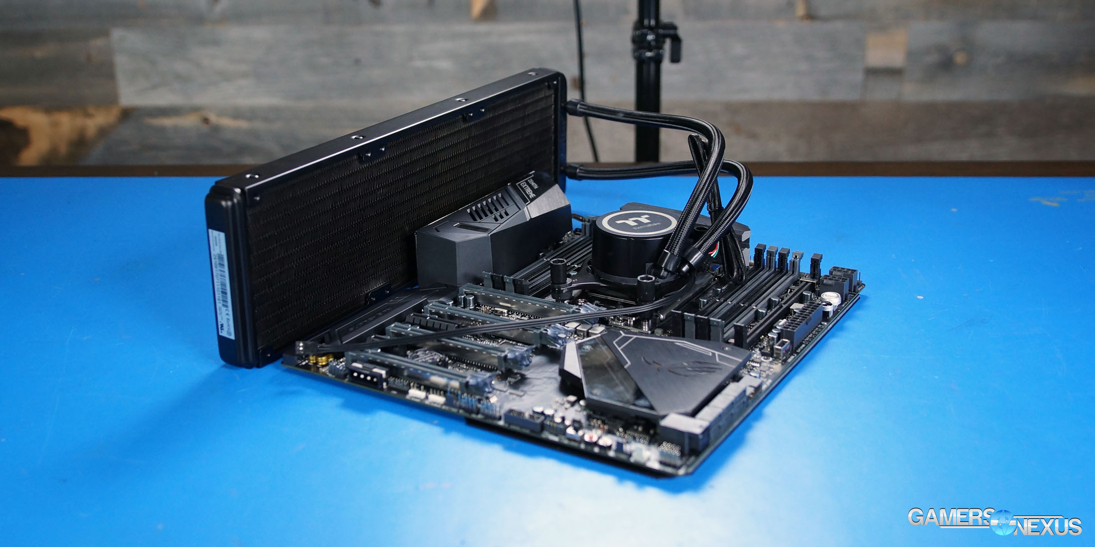
AMD’s done well with the installation mechanism for Threadripper, we think. It’s elaborate, and that’s not always good, but TR isn’t just elaborate for sake of being elaborate: The mounting socket specifies a torque of 1.5Nm (and Threadripper CPUs include an actual torque Torx wrench), which will help ensure even mounting pressure across a surface that could otherwise turn into a catapult. The mechanism braces the CPU in a way that protects it from users who may wrench-down the cooler inappropriately.
Installation is straight-forward: Hit numbers 1-2-3 in either ascending or descending order, depending on if the CPU is being socketed or removed. We show this procedure in the video. Once the three screws are loosened – but not removed – the top door will spring forth and reveal a lower retainer with the socket covers. Pop the retainer by applying light upward force on the blue tabs, then remove the translucent socket cover by sliding it up-and-out of the retention kit (do not push from the back). Slide the CPU in its orange tray into the retainer, then remove the socket cover and reveal the pins. Push it all back down and thread the screws in reverse order. Pretty easy, really.
As for cooler installation, TR has four threaded holes for coolers, with the top two (nearest the VRM) sitting closer together. Threadripper coolers appear to be specified with 1-2-3-4 ordering on each of the screws to ensure more event force applied during installation. Follow this order for each cooler.
AMD’s done a good job with their socket design on this one. It’s an expensive socket for damn sure, and that cost is passed on to the ODMs and users, but this is a place where it makes sense to invest the extra couple bucks. Protecting a large and awkwardly-sized CPU makes good sense, particularly when users will inevitably be attempting to retrofit coolers to the socket.
Now it’s just down to cooling manufacturers to fill the void. We’d minimally recommend considering thermal compound application in the screw hole areas of the CLC coldplates, if only to prevent potential hot air pockets from forming.
As for memory clearance, it wasn’t an issue on our kit – the keep-out zones are pretty well-marked on the Zenith board. Not every cooler will clear memory, though; kits with larger heatspreaders and coolers with fatter pump blocks can collide. The Kraken XX2 series and EVGA CLC series come to mind as potential collision paths, though we didn’t have immediate issues on our boards. Keep an eye on it.
Editorial: Steve Burke
Video: Andrew Coleman