Our GTX 1080 Ti SC2 review was met with several comments (on YouTube, at least) asking where the FTW3 coverage was. Turns out, EVGA didn’t even have those cards until two days ago, and we had ours overnighted the same day. We’ve got initial testing under way, but wanted to share the tear-down process early to spoil some of the board. This tear-down of the EVGA GTX 1080 Ti FTW3 ($780) exposes the PCB and VRM design, fan header placement, and cooler design for the FTW3. We’re working with GN resident overclocker ‘Buildzoid’ for a full PCB + VRM analysis in the coming days, but have preliminary information at the ready.
EVGA’s 1080 Ti FTW3 is one of the most overbuilt PCBs we’ve seen in recent history. As stated in our SC2 review, the EVGA team has gone absolutely mental with thermal pad placement (following last year’s incident), and that’s carried over to the FTW3. But it’s more than just thermal pads (on literally every component, even those that have no business being cooled), it’s also the VRM design. This is a 10+2 phase card with doubling and dual FETs all across the board, using Alpha Omega Semiconductor E6930s for all the FETs. We’ll save the rest of the PCB + VRM discussion (including amperage and thermal capabilities) for Buildzoid’s deep-dive, which we highly encourage watching. That’ll go live within a few days.
EVGA GTX 1080 Ti FTW3 Tear-Down
The rest of today’s discussion will stick with the non-power componentry and cooler configuration.
EVGA’s running six cables along the PCB: One on the backside (RGB LED nameplate), three fan headers on the frontside (all along the bottom), a power cable on the right side, and an LED synch cable at the top. The top cable synchronizes the LEDs from the MCU and the backplate, if desired.
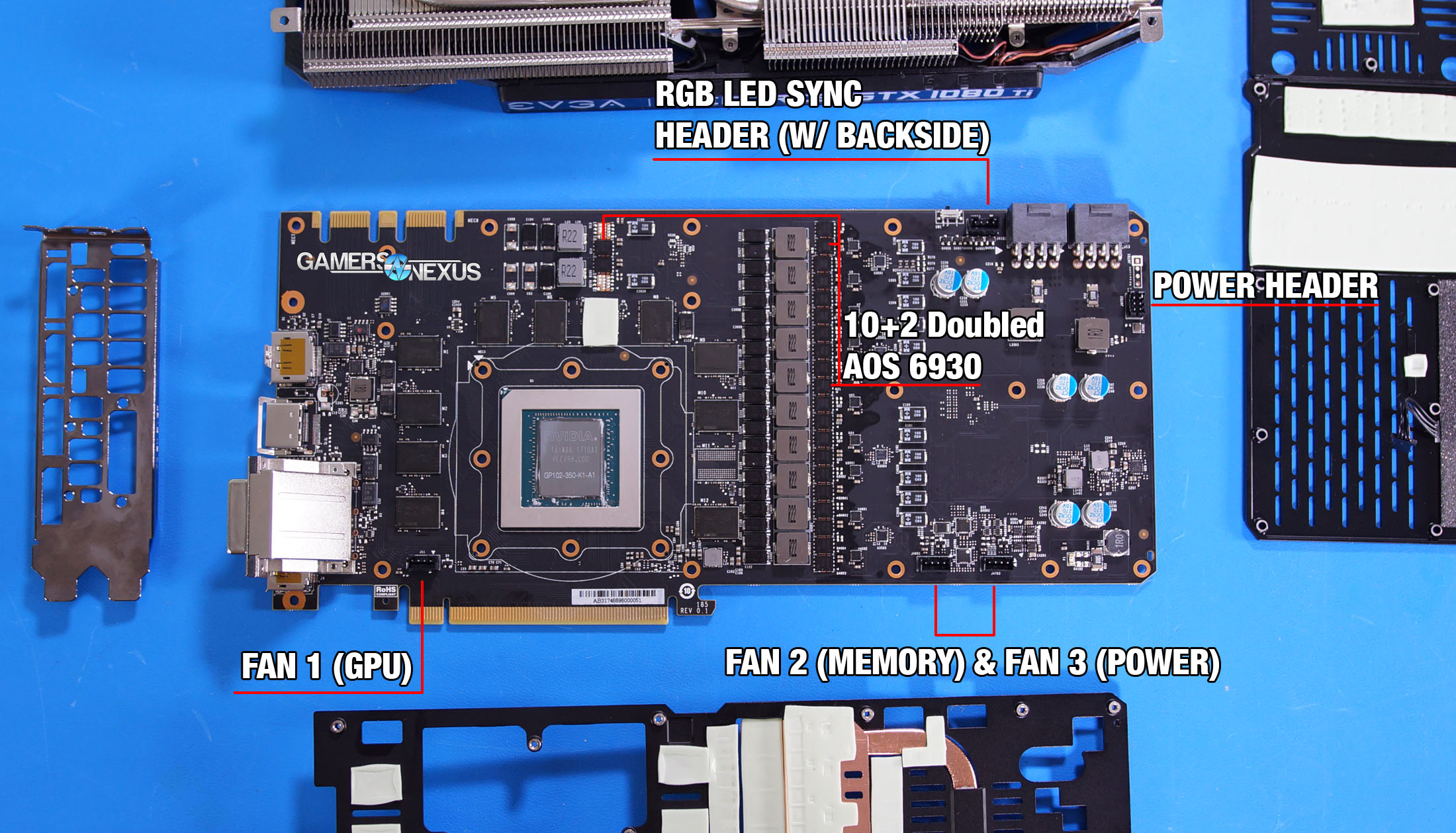
Each of the three fans is individually controlled by MCUs on the board, slaving to sensors that we’ve defined heavily in previous ICX content (initial deep dive, follow-up SC2 review).
The FTW3 heatsink sticks with overbuilding by design: Protruding cylindrical fins extend from the baseplate covering the middle VRAM modules and capacitor banks, further covered by a two-part finstack bridged by five heatpipes. A few different types of fins are used for the heatsink, too. L-shaped fins sit over the excessive VRM thermal pads to improve surface area contact to the thermal interface while still permitting airflow, better than straight fins for contact area. Straight fins are still used in regions that hover over the baseplate without contact, and squared fins sit in areas of the board that don’t need the extra airflow.
It also helps that the PCB is oversized, allowing for wider fans at lower RPMs (and without expanding width of the card).
We’ve got several interesting tests we’re running on this card, so be sure to closely follow the site & channel while we crank through those.
Editorial: Steve Burke
Video Producer: Andrew Coleman