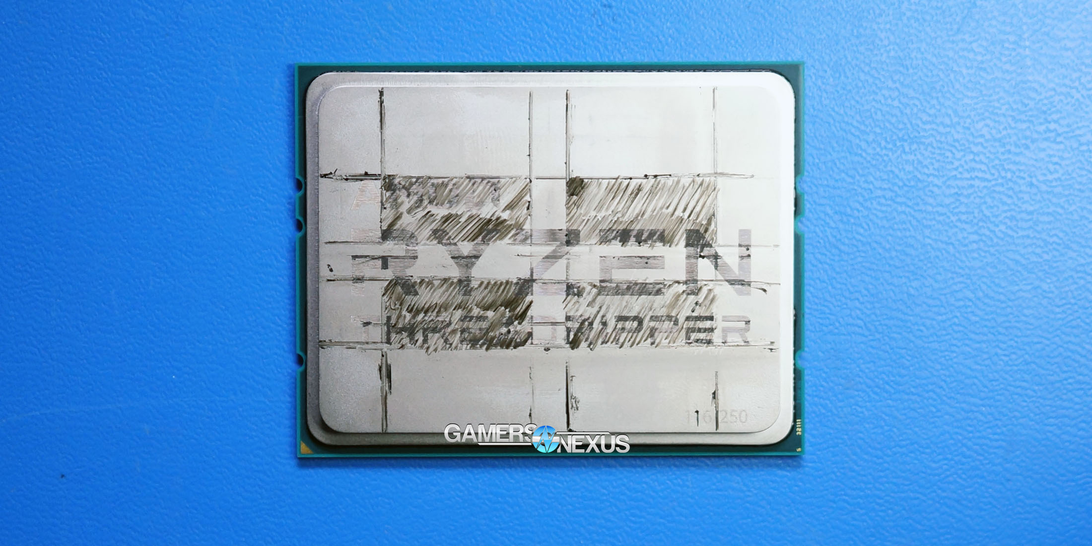
Following an initial look at thermal compound spread on AMD’s Threadripper 1950X, we immediately revisited an old, retired discussion: Thermal paste application methods and which one is “best” for a larger IHS. With most of the relatively small CPUs, like the desktop-grade Intel and AMD CPUs, it’s more or less been determined that there’s no real, appreciable difference in application methods. Sure – you might get one degree Centigrade here or there, but the vast majority of users will be just fine with the “blob” method. As long as there’s enough compound, it’ll spread fairly evenly across Intel i3/i5/i7 non-HEDT CPUs and across Ryzen or FX CPUs.
Threadripper feels different: It’s huge, with the top of the IHS measuring at 68x51mm, and significantly wider on one axis. Threadripper also has a unique arrangement of silicon, with four “dies” spread across the substrate. AMD has told us that only two of the dies are active and that it should be the same two on every Threadripper CPU, with the other two being branded “silicon substrate interposers.” Speaking with Der8auer, we believe there may be more to this story than what we’re told. Der8auer is investigating further and will be posting coverage on his own channel as he learns more.
Anyway, we’re interested in how different thermal compound spreading methods may benefit Threadripper specifically. Testing will focus on the “blob” method, X-pattern, parallel lines pattern, Asetek’s stock pattern, and AMD’s recommended five-point pattern. Threadripper’s die layout looks like this, for a visual aid:
Because of the spacing centrally, we are most concerned about covering the two clusters of dies, not the center of the IHS; that said, it’s still a good idea to cover the center as that is where the cooler’s copper density is located and most efficient.
Our video version of this content uses a sheet of Plexiglass to illustrate how compound spreads as it is applied. As we state later in the video, this is a nice, easy mode of visualization, but not really an accurate way to show how the compound spreads when under the real mounting force of a socketed cooler. For that, we later applied the same NZXT Kraken X62 cooler with each method, then took photos to show before/after cooler installation. Thermal testing was also performed. Seeing as AMD has permitted several other outlets to post their thermal results already, we figured we'd add ours to the growing pool of testing.
Testing Methods
Testing was performed using the NZXT Kraken X62 cooler at max speeds, using the same mounting force for each installation (same torque on the screws) and same threading pattern. We used an unbranded thermal compound from a liquid cooling factory for all tests; it is the same compound used on Asetek CLCs, and so we can more easily compare performance between stock Asetek patterns and our own applications. We are able to replicate the Asetek pattern using silk screens from the Asetek factory, in the event that the cooler is no longer in a fresh state.
Core voltage was controlled to 1.2v for the stock tests, and set to 1.3625V for the OC tests. All testing was conducted with the AMD Ryzen Threadripper 1950X 16C/32T CPU socketed in an ASUS Zenith Extreme X399 motherboard. Our voltage for stock tests is a little generous: We wanted something stable and unchanging, and 1.2V provided that. We almost never observed core voltage fluctuations with this setting, whereas lower voltages would attempt to spike on occasion. The multiplier for the overclocked test was set to 40x on all cores.
We’ve found HWiNFO64 to be the most accurate software for monitoring Threadripper right now, as AMD has collaborated with the HWiNFO team directly to ensure accuracy of the thermal readout. The Tdie readout in HWiNFO is an aggregate measurement of all thermal sensors across the dies and IHS, of which there are 36. Tdie also removes the TCTL offset of 27C, so we are reading without the +27C TCTL offset. We employ a current clamp at the EPS12V cables to monitor amperage provided to the CPU, which is later aligned in a spreadsheet with Vcore, frequency, Tdie, pump/fan RPM, Tliquid, and ambient air temperatures. This allows us to ensure consistency between tests, as we’re able to cross-reference power draw, Vcore, and temperatures to double-check that the burn-in applications are power cycling in a predictable and consistent fashion.
Prime95 28.5 is being used for burn-in. We attempted to use 29.2 with 8K/8K FFT sizes at first, but encountered behavioral issues that we don’t yet understand with Threadripper. This is anomalous and likely more an issue with how that particular version works. 28.5 performed more predictably and power cycled at known intervals, making it easier to find peak average and 10s peak temperatures. Burn-in runs until the CPU and liquid both reach steady state temperatures, with ambient monitored actively with a thermocouple reader. We report values as Delta T over ambient. As a general rule, ambient is in the 23-24C range (common fluctuations of +/-1C), but we account for this in ambient monitoring. You could roughly add ~24C to get the originally reported Tdie measurement. We have a known test-to-test variance of +/-1C with this approach.
Thermal Paste Application Methods on Threadripper (Photos)
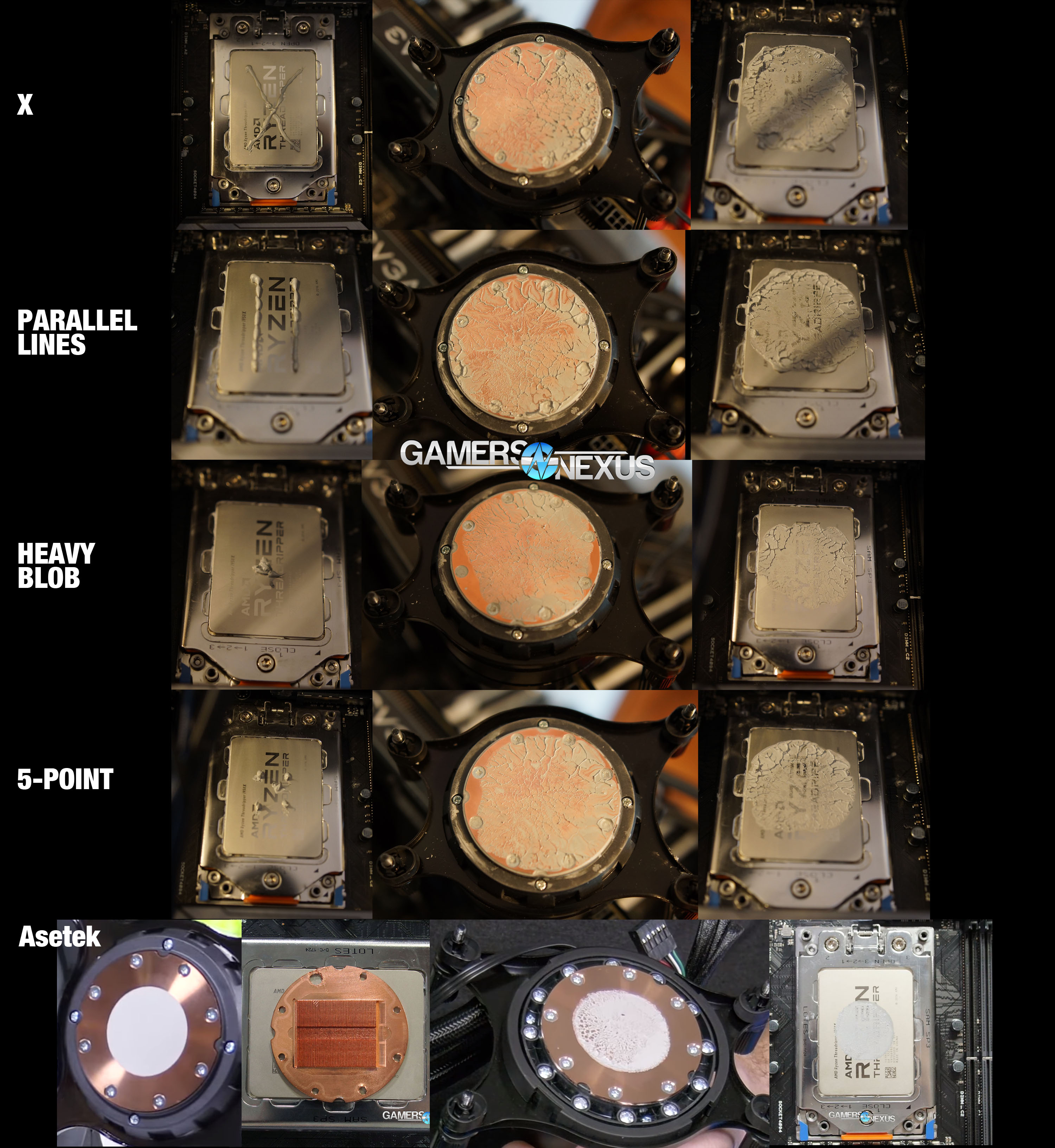
Here’s how it ended up looking in photos.
These images show the application after the cooler was torqued down fully, run through our thermal burn-in, and then removed. This has a huge “your mileage may vary” element to it, and would change each application just because you’re going to use at least a slightly different amount of paste each time, with at least a slight variation to where that paste is placed. The plexiglass test was a nice idea, but once we actually applied real mounting force to the thermal paste applications, it was clear just how much more spread you get from the retention kit. Once in a real-world application, the plexiglass method doesn’t remain all that representative of what we’re doing.
Here’s a photo of the small blob application, which will be useful momentarily:
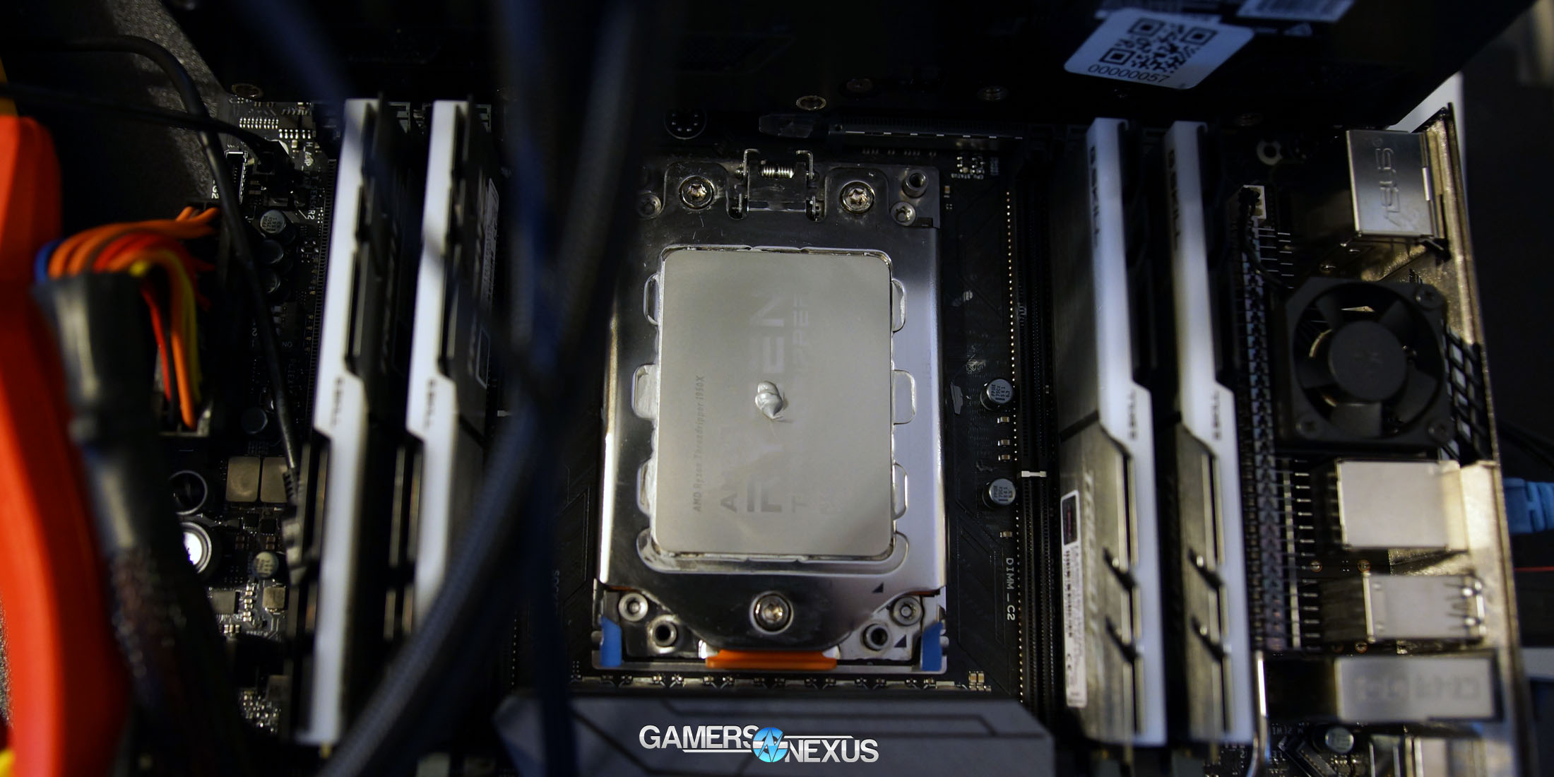
Above: We present our masterpiece -- "Small blob" -- the lightest application of compound we tested, alongside Asetek's stock compound.
Results
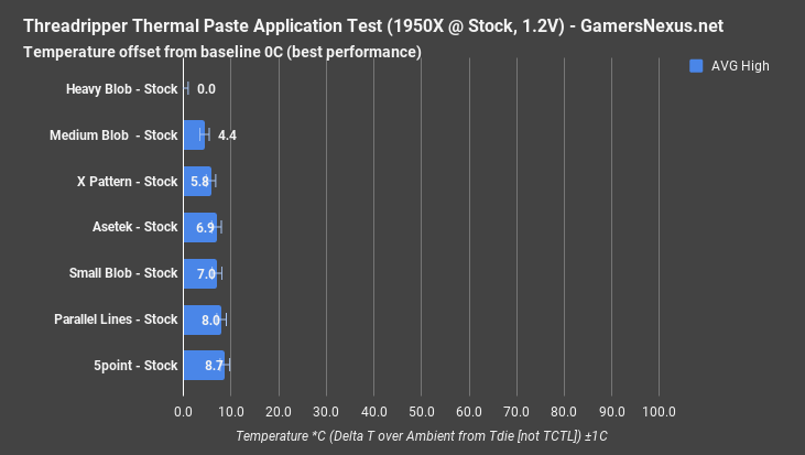
Note: The below charts are presented as an offset from baseline 0, with the best performer set to "0." This is a delta value -- lower is better, and higher numbers show temperature increase from baseline. AMD is presently only allowing Linus, Hot Hardware, and TechRadar to show temperatures, so we're showing an offset value from baseline 0. That's the temperature difference from thermal compound, in case anyone at AMD is confused, which is what we're testing. We refused to take down the video or article as neither contains more information than what the company has already permitted to be published by AMD's favored reviewers. Note also that we never published comparative figures versus other CPUs, so it's pretty silly to consider this as anything more detailed than what others have already published. Regardless, strictly as a show of good faith on our end, we decided to temporarily change the charts to be offset from baseline 0 values. We were not forced to do this (AMD actually wanted the content pulled -- which we are refusing to do, seeing as others were given permission to publish thermal data and, frankly, this isn't any more information than is out there), but decided to offer the middle-ground just to show a good gesture. If you want the original charts, which are a bit easier to read and more condensed, they're still in the video -- and that's not changing. Want the original charts? Check 15:20 in the video and 18:55 for the OC chart.
10-Second Peak Thermals (Stock, offset from baseline 0)

AVG High Thermals (Stock, offset from baseline 0)
AVG Liquid Thermals (Stock, baseline offset from 0)
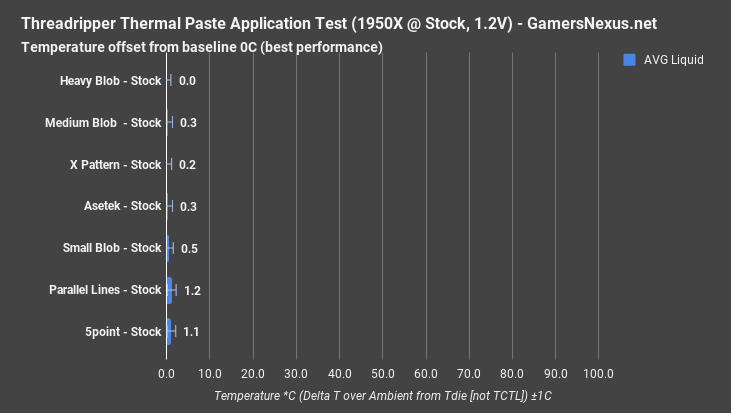
Assuming your ultimate goal is just to cover the whole IHS, it seems that application method doesn’t matter too much so long as a sufficient amount of compound is located centrally. Our “small blob” test uses a sparing amount of compound – shown above – and managed to perform similarly to the Asetek pre-application and the double-line pattern. We think this is partly because of the uneven spread of our double-line application, and possibly because the double-line pattern ended up bordering on excessive compound – to a point where it may be inhibiting transfer of energy at least partially.
Our “X” pattern gave the most overall coverage once we corrected the lines to better intersect the dies, and ended up covering the entire coldplate of the X62. This gave us a measurable and repeatable performance improvement of 2-3C, depending on which numbers you’re comparing. This is pretty damn close to our error margins, though skates by just barely. The only real reason the “X” pattern is performing well is because we’ve covered more of the coldplate, though there’s a limitation to efficacy of spread as you start bumping into the seal boundaries toward the screws in the plate. In the very least, we’re preventing air pocket hotspots from forming in those screw holes, which do sit right over the dies.
Following AMD’s application method, we ended up closer to 44C – not that distant from the other tests, and also within error margins for most of its neighbors. It could be better, though. AMD’s recommended application method leaves a lot of room for the user to play: There’s no reason that the five-dots method recommended wouldn’t work just as well as the others, it’s just a matter of how much paste you apply. With larger dots, assuming it’s not excessive, we should more or less match performance of other nearby application methods. We followed AMD’s guide as best we could, but there’s room for bigger dots.
The most interesting test was the “Heavy Blob” method. We did two applications of this one, with the first using a significant amount of thermal compound dead-center of the ‘Z’ in “RYZEN.” The second test used about 25% less compound, and still managed a 39.6C delta T over ambient average performance. The larger version of this blob operated at around 35C delta T over ambient, a significant performance uplift over some of our other test patterns – certainly a big swing from the Asetek default pattern.
Again, we think that this is just a matter of relying on the cooler’s own mounting pressure to spread the compound out evenly across the IHS, rather than trying to more manually spread the coverage. The downside is that you’re sort of guessing at how much you need to cover everything. That’s the only real disadvantage to the blob method – it’s easier to gauge coverage with an X, AMD’s recommended five dot approach, or with the parallel lines “road” approach. The dot does ensure that we don’t end up with any odd hotspots within the inner diameter of the coldplate, but we just have to use enough to make sure there’s full spread outward.
We think the "heavy blob" performance benefit is largely because of how much was used -- it's not fully shown or appreciated by the picture, but the heaviest blob did manage to eliminate any of the occasional air pockets in the inner diameter of the coldplate. This method also spread outward and reached out to the countersunk screws, where the paste filled a few of the holes that sat over the dies (those which are not covered were not over dies anyway, it seems -- they were located over 'blank' areas of the IHS).
What’s not shown here is our test without thermal paste, which resulted in clock throttling, as you might expect.
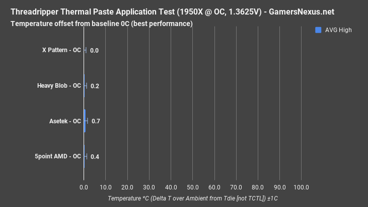
(This chart is rather simplified -- if you want to see all the data from the original chart, you can go to the 18:55 timestamp. This link makes it easier.)
As for overclocking results, well, we didn’t have a good enough cooling solution to find a difference. The CPU was pushing 21-26A down the EPS12V at this point, or around 260-326W, and so was running hotter than our Kraken X62 could handle in its stock state. We’d need heavier duty cooling to get thermals down to a point where a thermalpaste difference is visible. At this level of power consumption, the cooler can be thought of as “bottlenecking” our cooling performance to a point of obfuscating something as relatively minor as compound application differences. If you’re wondering why this chart doesn’t contain every application method, it’s because it was pretty apparent what was happening by this instance in testing – no point in trying more methods when our cooler is the limiter.
Conclusion: The “Best” Thermal Paste Method for Threadripper
The only real conclusion is that covering the whole cooler coldplate is worth it. Ensure no air pockets form in the gaps between thermal compound lines and performance will be fine. There’s no perfect method here. Given our approach, a giant blob proved effective – but it’s also less reliable and requires some practice to know just how much compound to use. AMD’s five-dot pattern requires a bit more precision to line-up where the four dies are, but can work fine with dots that are large enough. The X-pattern is perhaps easiest to gauge spread of coverage but, just like all other approaches, requires enough compound to cover potential hotspots and ensure the inner circle of the IHS still has sufficient contact to the coldplate’s densest mass of copper.
This comes down to experience and preferences: We have the most experience with the “blob” method, and so that one performed best as our experiential bias is going to favor that approach to application. We know how much to use with the blob approach, and so there’s enough to ensure full spread across the IHS hotspots. The X pattern could work just as well, as could the five-dot pattern. The takeaway is to use a lot of thermal paste, within reason. Too much will still hurt performance once entering territory of being excessive, but excess should mostly squish outward. It’s just when there’s build-up of compound around the perimeter of the coldplate that there’s potential for performance loss.
Editorial, Testing: Steve Burke
Video: Andrew Coleman